The TCRT5000 is an optical sensor with transistor output, it is very commonly used in the design of follow line robots, this post will show how to assemble the wiring diagram and make mounting this sensor. For the practical means to test I will use an Arduino to test it.
Before you begin, some very important information needs to be highlighted, and for that, read DATASHEET component is the best option to extract this informations.
How It Works
This sensor is basically composed of an LED emitting infrared (Light that in this frequency [Hz] is not visible to humans) and a phototransistor responsible for filtering natural light and capture infrared signals or not. It has a shield that separates the emitter and the receiver, depending on the reflectivity of the surface it is able to detect the color (On a BLACK and WHITE scale) that surface in question.
Operating Characteristics
• Dimensions (L x W x H in mm): 10.2 x 5.8 x 7
• Operating distance peak: 2.5mm
• Operating Distance with efficiency greater than 20%: 0.2mm to 15mm
• Current consumption: 1mA
• Wavelength Emitter: 950nm
Electrical Circuit
This circuit is just one example of assembly and use of this sensor, you can change your settings to suit certain situations or specifications, always following what was specified in the DATASHEET.
Material
1x - 10KR resistor (Brown, Black, Orange)
1x - 510R resistor (Green, Brown, Brown)
One Arduino to be used as a controller
Assembly
How LEDs and transistors are polarized, note the bevelled side of the sensor to the correct position, incorrect junctions may damage the sensor.
In the above circuit the resistor R2 (Cited in Figure 2) (10KR in Figure 3) is used as a "pull up" resistor. It ensures that the output is at a high level while the phototransistor is not conducting, it is what happens when there is no incidence of infrared light on it and prevents a short circuit when the phototransistor conducts.
Increasing the value of R2 (Cited in Figure 2) (10KR in Figure 3) means, respecting the manufacturer limits (See DATASHEET), increase the sensitivity of the sensor, as it will be easier to put the phototransistor output at low level . Conversely, reducing the value of R2 (Cited in Figure 2) (10KR in Figure 3), it also reduces the sensitivity of the sensor. (Ideally placing a Trimpot "For example 20kR" in series with a resistor "For example 10KR" allows for an adjustment at runtime environment to this sensor)
 |
| Figure 1 - Image of a sensor TCRT5000 |
How It Works
This sensor is basically composed of an LED emitting infrared (Light that in this frequency [Hz] is not visible to humans) and a phototransistor responsible for filtering natural light and capture infrared signals or not. It has a shield that separates the emitter and the receiver, depending on the reflectivity of the surface it is able to detect the color (On a BLACK and WHITE scale) that surface in question.
Operating Characteristics
• Dimensions (L x W x H in mm): 10.2 x 5.8 x 7
• Operating distance peak: 2.5mm
• Operating Distance with efficiency greater than 20%: 0.2mm to 15mm
• Current consumption: 1mA
• Wavelength Emitter: 950nm
Electrical Circuit
This circuit is just one example of assembly and use of this sensor, you can change your settings to suit certain situations or specifications, always following what was specified in the DATASHEET.
 |
Figure 2 - Schematic Circuit |
1x - 10KR resistor (Brown, Black, Orange)
1x - 510R resistor (Green, Brown, Brown)
One Arduino to be used as a controller
Assembly
How LEDs and transistors are polarized, note the bevelled side of the sensor to the correct position, incorrect junctions may damage the sensor.
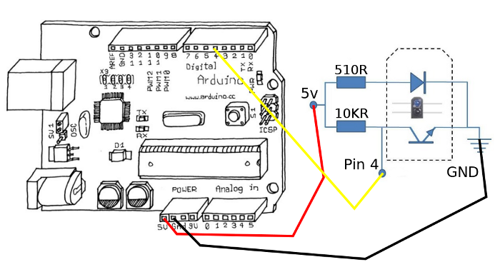 |
| Figure 3 - TCRT5000 + Arduino |
Increasing the value of R2 (Cited in Figure 2) (10KR in Figure 3) means, respecting the manufacturer limits (See DATASHEET), increase the sensitivity of the sensor, as it will be easier to put the phototransistor output at low level . Conversely, reducing the value of R2 (Cited in Figure 2) (10KR in Figure 3), it also reduces the sensitivity of the sensor. (Ideally placing a Trimpot "For example 20kR" in series with a resistor "For example 10KR" allows for an adjustment at runtime environment to this sensor)
Note that we used the PIN 4 in Arduino, if you want to read color tones ranging from black to white you should use a PWM pin of the arduino, as demonstrated in this case the sensor only returns either black or white.
Code
TCRT5000 (Reflective Optical Sensor) with Arduino
 Reviewed by AJ Alves
on
terça-feira, novembro 06, 2012
Rating:
Reviewed by AJ Alves
on
terça-feira, novembro 06, 2012
Rating:
Reviewed by AJ Alves
on
terça-feira, novembro 06, 2012
Rating:


 with Arduino")


Nenhum comentário:
Postar um comentário