One of the main concerns of a project that will be powered by batteries is knowing exactly when they are about to discharge. There is a simple way to measure this, so let's get to practice.
 |
Figure 1 - Battery level and Arduino
|
The sensorThere is some information that is crucial to build this circuit, the first is the properties of the battery in use, for example, for this experiment we will use two sealed 6 V lead acid batteries, 4.5 Ah capacity, in fluctuation from 6.75 to 6.90 V , in cyclic from 7.05 to 7.2 V, each. As there will be two batteries in series, the values we will use are 12 V, 4.5 Ah capacity, fluctuating from 13.5 to 13.8 V, in cyclic from 14.1 to 14.4 V, total.
At the other end, we will use an Arduino analog port, which in the case of Arduino Uno, operate at a resolution of 10 bits and 5 V.
 |
Figure 2 - Scheme of a Voltage Divider and its formula
|
|
The sensor itself, consists of a voltage divider, as seen in Figure 2, is a simple arrangement of two resistors and the ability to read the voltage between them. This output voltage (V_OUT) will always be a fraction of the input voltage (V_IN) in relation to the values of resistors R1 and R2.
The first precaution that we must take is that the value of V_OUT never exceeds the value of 5 V, which is the operating limit of the Arduino's analog port. So first we must find a reason for this value in the battery voltage that we will use, but not the nominal battery voltage, which is 12 V. For safety, we will use the maximum value that the battery can reach when charged or in voltage variation, which is of 14.4 V, here we will round (Always upwards) to 15 V.
Therefore, the ratio is 3 (15V / 5V = 3). However, as a precaution, since an error will cause damage to the Arduino board, we will use 4 as the reason.
 |
| Figure 3 - Partially assembled circuit |
Notice in Figure 3 that we use a IC (Integrated Circuit), the L7805, a voltage regulator, and two ceramic capacitors, C1 (0.33 uF) and C2 (0.1 uF), these three elements are only used to transform the 12 V voltage that arrives from the battery, to 5 V, and thus power the Arduino. Therefore, more detailed explanations about them are outside our scope.
To simplify the understanding, we use 4 (The calculated reason) different resistors of 1 MR each ( Continue reading to understand why 1 MR ). If we calculate, using the formula of the voltage divider, the resulting voltage (V_OUT) at each of the points P1, P2, P3, P4 and P5, we would have (Remember that series resistors have their value added):
- Vout = R2 / R1 + R2 * Vin => Vout = 4000000R / (0R + 4000000R) * 12V => Vout = 12V
- Vout = R2 / R1 + R2 * Vin => Vout = 3000000R / (1000000R + 3000000R) * 12V => Vout = 9V
- Vout = R2 / R1 + R2 * Vin => Vout = 2000000R / (2000000R + 2000000R) * 12V => Vout = 6V
- Vout = R2 / R1 + R2 * Vin => Vout = 1000000R / (3000000R + 1000000R) * 12V => Vout = 3V
- Vout = R2 / R1 + R2 * Vin => Vout = 0R / (4000000R + 0R) * 12V => Vout = 0V
Note that everything is a game of balancing the resistor values from R1 to R2, and for our needs, we will do the reading in P4, which will have a voltage reading in a maximum of 3 V, as shown in the calculation, and the values of R1 and R2 are 3 MR and 1 MR, respectively.
The circuit
So we already have the list of materials:
- 1x - Arduino
- 2x - 6V Sealed Lead Acid Battery
- 1x - CI L7805
- 1x - 0.33 uF ceramic capacitor
- 2x - 0.1 uF ceramic capacitor (Continue reading to understand why 2x)
- 4x - 1 MR resistors
 |
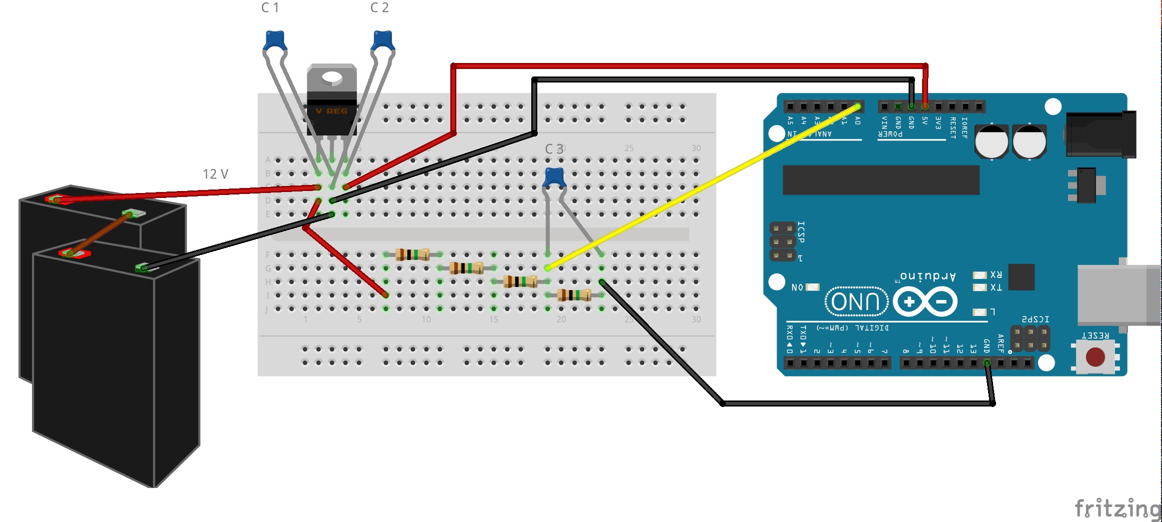
| Figure 4 - Assembled circuit |
It is the time to explain the two points that remain unexplained, the first is why the resistors of 1 MR. The value of the resistors was made according to the current drain, which naturally occurs in our load level measurement system. Note that there could be 4 resistors of 5 KR, or 4 of 1 KR, or 4 of 330 R, or even 4 of 1 R, since, for the calculation of the voltage divider, the final result would be the same, calculate yourself. What changes is the amount of current that would be lost in that system. See, for example, if there were 4 resistors of 1KR, according to Ohm's Law, the loss would be: U = R * i => 12V = 4000R * i => i = 12V / 4000R => i = 3mA; 3 mA constantly, but as we chose 4 resistors of 1 MR, we have: U = R * i => 12V = 4000000R * i => i = 12V / 4000R => i = 0.003 mA; 0.003 mA of constant loss. So, 0.003 mA, especially for a battery with the characteristics we are using (4.5 Ah capacity), is a very good value. We could use 10 MR resistors (It would be 0.0003 mA) if we were going to use low capacity batteries.
However, there are limits for the use of resistors. Down, if we use very small resistors, we would lose more current and depending on the type, damage the battery itself, since each type has a maximum current drain limit (Ours limit is 45 A/5s). Up, using very large resistors, we will have problems with the reading capacity on the part of the Arduino.
According to the ATmega328 Datasheet (Used in Arduino Uno, for example) it recommends that the output impedance of the circuit connected to the analog input pin, be up to 10 KR for reading good results. Higher values, as shown in the previous paragraph, provide less current, it affects the capacity of Sample and Retention Capacitor that is connected to the analog pin, to charge. It means that the time for the ADC (Analog to Digital Converter) to report a stable value, will be longer, thus affecting the ability to obtain readings at the desired frequency or time.
There is also the leakage current of each pin (Analog and Digital), according to the Datasheet, is about ± 0.001 mA. It means that our divider, with 4 resistors of 1 MR, will not only take longer to be read, it will also not be accurate or never be read accurately at all, no matter how long we wait or how often we repeat the measurement.
That is why the C3 capacitor (0.1 uF) comes into play, it is in parallel to the smallest resistor (R2), its function is assist the Sample and Retention Capacitor and filtering the parasitic capacitance effect that can affect the other analog ports.
I believe it was already clear, but it costs nothing to point out, this circuit was set up to read the charge level of a 12 V battery using the Arduino. Batteries of other voltages, especially for higher voltages, require different configurations.
The code
For Vout we already have all the information necessary to calculate its value, this being only a proportional relation between the maximum voltage that will arrive at the port (3V, as calculated) in relation to the maximum 5 V of the analog port, divided into a resolution of 1024.
For Vin, just apply the voltage divider formula. Finally, knowing the nominal battery capacity (12 V) and what is actually being read from it (Vin), it is possible to calculate the percentage of battery charge.


 Reviewed by AJ Alves
on
quarta-feira, janeiro 20, 2016
Rating:
Reviewed by AJ Alves
on
quarta-feira, janeiro 20, 2016
Rating:


 with Arduino")


Nenhum comentário:
Postar um comentário